
14+ Sequence Diagram Explained Robhosking Diagram
Ceiling Fan regulator circuit By using Triac, Diac and variable resister elements we can create effort less ceiling fan regulator and this regulator circuit regulates ceiling fan speed smoothly. Ceiling Fan regulator connection diagram Construction and Working
Ceiling Fan Regulator Connection Diagram Modern Forms Fans
Ceiling Fan Regulator Circuit Connection Diagram, How to connect the regulator for the ceiling fan? The circuit diagram /wiring diagram is explained. Insid.
electric fan speed controller or regulator Electronics Forum (Circuits, Projects and
2 pin Terminal Block Circuit Diagram for the AC Fan Regulator The AC fan regulator circuit diagram is given below. The 220V AC mains voltage is given as the input to the one terminal of the fan (load) and the other terminal of the fan is connected to the one leg of the 10K ohm resistor.

Table Fan Regulator Wiring / How To Connect Fan Regulator Ceiling Fan Regulator Connection
A simple electronic ceiling fan regulator circuit using a triac and a diac is a common type of circuit which is used to control the speed of a ceiling fan. This circuit basically works using phase control principle, in which the voltage supplied to the fan motor is varied by controlling the firing angle of the triac.

fan regulator connection YouTube
is videome aap sikhenge kaise ek fan regulator k connection kiye jate hai kaise fan regulator ki wiring ki jati hai . how to install fan regulator full delta.

2 Wire Ceiling Fan Wiring Diagram
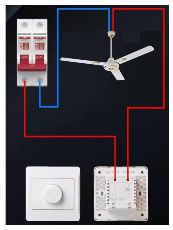
First, we will be the circuit breaker of the live wire "L" to the fan regulator into the fire line end, the fire line out of the terminal to the ceiling fan motor, ceiling fan motor and then connected back to the circuit breaker neutral wire "N" can.
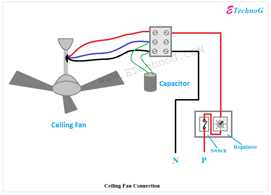
[Proper] Ceiling Fan Connection with Regulator, Switch and Capacitor ETechnoG
Voltage Regulator Circuit Connection Circuit Diagram of Voltage Regulator using TRIAC, DIAC Operation of the Electronic Voltage Regulator Circuit Advantages of Simple Fan Regulator Circuit Simple Electronic Voltage Regulator

Best Ceiling Fan Regulator to Save EnergyConnection & Working Zaroori Baatein
Fan Regulator Circuit Explanation: The triac based regulator circuit is present between load and source. As you can see in the circuit diagram diac connects to the gate of the triac.

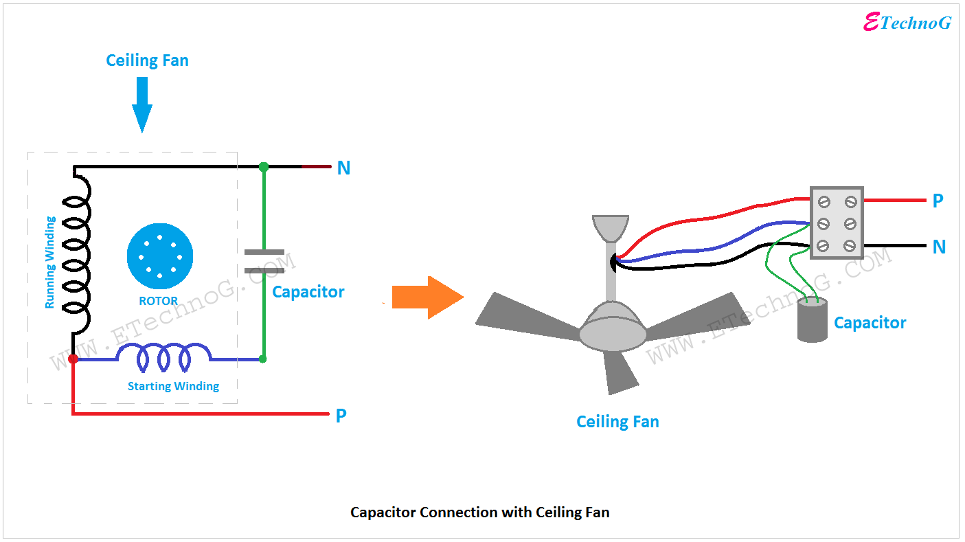
table fan wiring diagram with capacitor
Installing and wiring of a ceiling fan is a very simple matter even a beginner also can easily connect a ceiling fan and fan regulator to the house wiring co.

Wiring Diagram Of Ceiling Fan With Regulator
Wiring Diagram of 3 Speed Fan Capacitor Below is a basic and simple figure of an external connection that links the ceiling fan, fan speed regulator, and ON/OFF switch to a single-phase power supply at home. The internal connection of the running coil/winding, starting coil/winding, and the capacitor is also shown.

Regulator Connection With Ceiling Fan Fan Regulator Connection Electrical House Wiring
Fan Regulator Connection Circuit Diagram: This diagram shows how to make a fan regulator, in this circuit, we use a ceiling fan, a DP MCB ( Double Pole Miniature Circuit Breaker ), a power socket, a 3-pin plug, a fan regulator, and a fan capacitor.
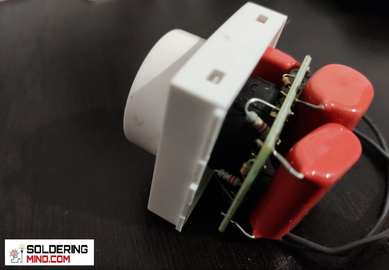
Simple Fan regulator circuit Diagram Soldering Mind
https://ryb.com.bd/ visit my website http://rybonline.com/ #fan 3connection with 3regulatorFAN #REGULATOR# CONNECTIONhow to connect fan regulator to the #swi.
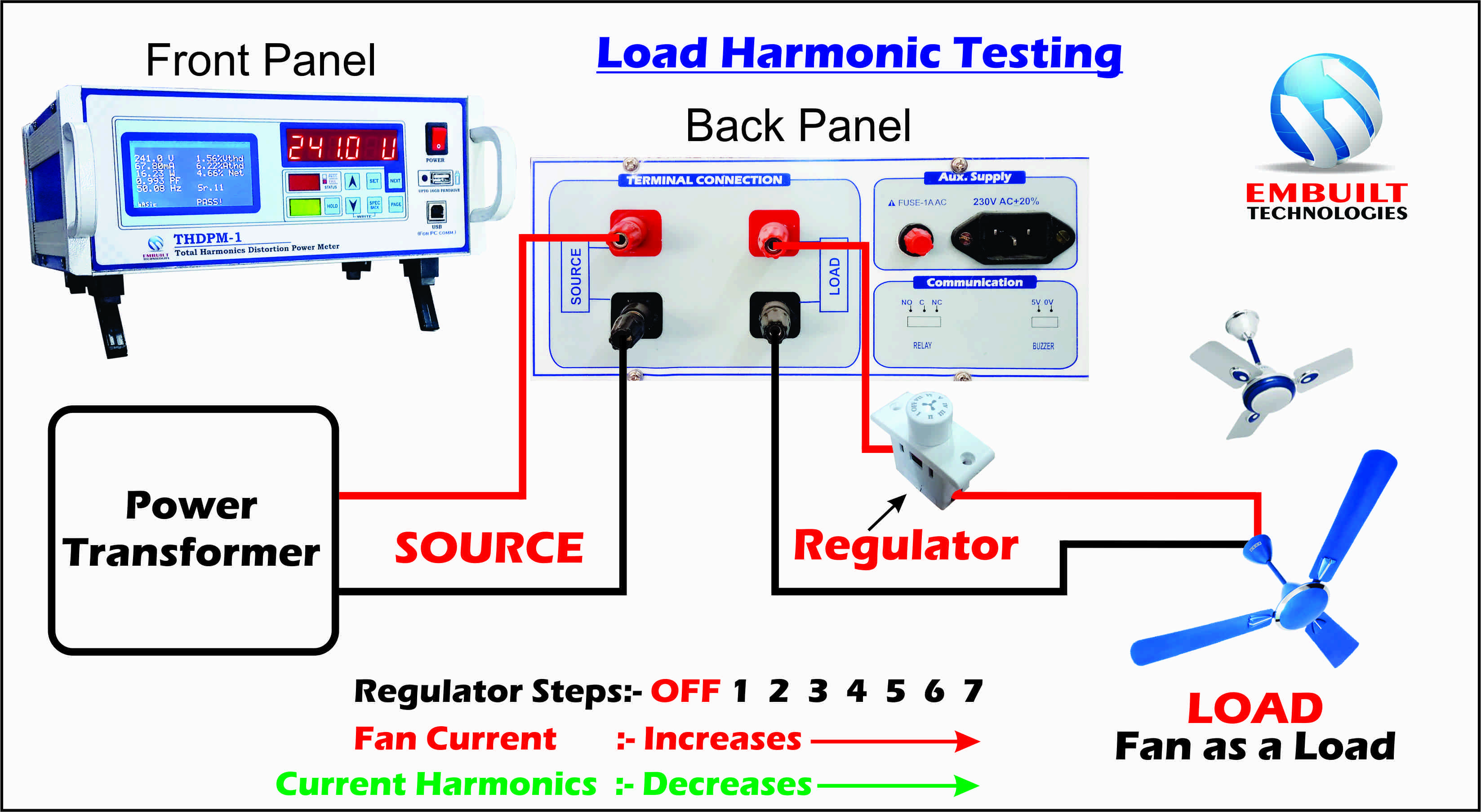
Fan Regulator connection & Harmonic testing LED Driver Testing with THD Measurement
Simple fan regulator circuit diagram Components required for voltage regulator circuit Triac - BT136 Diac - DB3 Resistor - 10K Potentiometer - 100k Capacitor - .1uf/400v Capacitor. 230v - 250v AC 50 Hz Ceiling fan ( Below 200W)

old fan regulator connection diagram Wiring Diagram and Schematics
A ceiling fan regulator wiring diagram is a diagram that shows the connections of all the different components that make up a ceiling fan. It is used to illustrate how all the parts fit together and how they will look when wired correctly.

table fan regulator connection diagram,table fan regulator wiring,how to table fan regulator
A single fan and light control using an individual switch is a very commonly used wiring circuit in house, offices, etc. In the circuit, the phase line is connected parallel to the one pole of the two SPST switches and the neutral line is connected parallel to the neutral terminal of both fan and light. The terminal of switch S2 is connected.
How to Connect Fan Regulator? UnitedStar
Diagram of Fan Regulator Connection: Components needed For this Project: You can get the components from any of the sites below: Ceiling Fan [See Buy Click Amazon] 2.5uf Capacitor [See Buy Click Amazon] Fan Regulator [See Buy Click Amazon] Switch [See Buy Click Amazon] Terminal Block [See Buy Click Amazon] *Please note: These are affiliate links.
